MAINTENANCE MINDER 2® OVERVIEW
Power unit is equipped with the Maintenance Minder 2® Controller. It will:
• Automatically keep track of maintenance intervals and warn the user when maintenance is due, based on the number of lifts.
• Record low voltage occurrences.
• Record high temperature faults.
• Record maximum run time faults, when a single operation exceeds the maximum continuous run time limit.
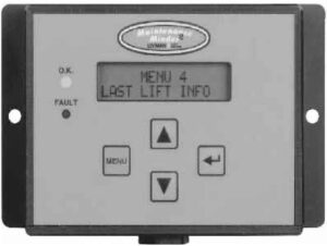
• Give helpful trouble-shooting information on MENU 4, “Last Lift Info”.
FAULTS CODES
A decal in the power unit enclosure lists the following signal codes for these faults:
1 BEEP Service Fault (reached the number of lifts when maintenance is due)
2 BEEPS Low Voltage Fault (check battery condition and power line connections)
3 BEEPS Max. Time Fault (exceeded the maximum continuous run time allowed)
4 BEEPS High Temperature Fault (unit will not run until motor cools)
All faults signals will be repeated FOUR times, except the Service Fault signal. Controller will prevent power unit from operating during the time period when a fault signal is sounding (about 5 to 10 sec.) except for the Service Fault signal. The controller is also equipped with an anti-doorbelling feature, which prevents rapid ON/OFF operation of the power unit.
RESETTING after MAINTENANCE IS PERFORMED
To RESET the Maintenance Minder 2® after maintenance has been performed:
1. Go to MENU 2, hit “ENTER”, and toggle down to the “Reset All Info” screen.
2. Press and hold the hidden RESET button under Maintenance Minder 2® logo at top of faceplate.
3. Follow the instructions on the screen regarding a second button, which must be pressed to complete the reset operation.
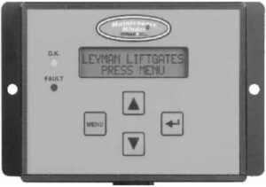
MAINTENANCE MINDER 2® CONTROLLER MENUS
(Press MENU)
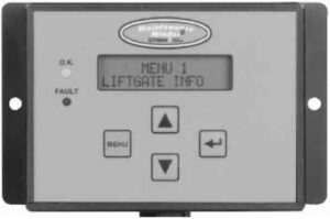
MENU 1 – LIFT GATE INFO
(Press ENTER, then ARROW DOWN for each item)
Model Number, Serial Number, Manufacture Date, Vehicle ID, Hardware Version, Firmware Version, Software Version.
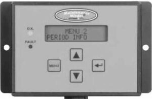
(Press MENU and ARROW DOWN once)
MENU 2 – PERIOD INFO (data for current maintenance period)
(Press ENTER, then ARROW DOWN for each item)
Number of Lifts (gives the number during this maintenance interval and the set number when maintenance is due)
Motor ON (total motor run time in minutes for this maintenance period)
Service Fault (number of times gate was operated PAST the maintenance limit)
Max. Time Faults (times motor exceeded its maximum allowable continuous run time)
High Temperature Faults (times thermal switch in motor tripped, if switch provided)
Low Voltage Faults (times low voltage occurred)
Reset all Info (Reset data after performing maintenance, once maintenance limit is reached – see reset instructions on previous section)
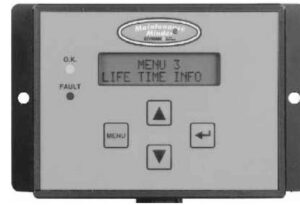
(Press MENU and ARROW DOWN twice)
MENU 3 – LIFE TIME INFO (data for the total life time of the gate)
(Press ENTER, then ARROW DOWN for each item)
Same items will appear as under PERIOD INFO, except this is LIFE TIME data.
Reset History (reviews history for each maintenance interval)
Press ENTER, then ARROW DOWN to show history. Most recent period is the highest #. Screen shows Period #, # of Lifts,
and Total Run Time in minutes.
(Press MENU and ARROW DOWN three times)
MENU 4 – LAST LIFT INFO (Trouble Shooting Screen – it records data that occurred during the last lift made)
(Press ENTER, then ARROW DOWN for each item)
Supply Voltage (first voltage is the minimum voltage that occurred during the last lift – if below 6 volts gate will stop / second voltage is the supply voltage just before gate operation, must be at least 10 volts).
Motor ON (motor run time in seconds during last lift, gate will stop at 180 seconds).
Window Time (time in milliseconds during the last lift that the voltage dropped in between 6 and 8 volts – must not be any longer than 3 seconds or gate will stop).
NOTE:
Controller has an anti-doorbelling feature. Motor will not operate if UP switch is toggled rapidly. This prevents welding of the start solenoid contacts.